…or “Living Without A Shack: Part 2”!
This is a page to detail how I remotely operate my Elecraft K2 HF transceiver via my home network. The method used should apply to pretty much any amateur transceiver that can be controlled by serial port. Note the aim of this project is to operate the radio across a LAN where bandwidth is plentiful as opposed to many remote radio projects that are aimed at operation across the Internet with all the additional bandwidth and latency constraints.
Space constraints and family life prevent me from having a dedicated ‘shack’ set up in the house so this is my solution – a small HF radio setup tucked away in a utility cupboard but accessible via the home wireless network allowing operation from a laptop computer. I already use remote desktop (VNC) methods for controlling radio receivers but haven’t found it responsive enough with the hardware I have for use with a transceiver. Also, using a ‘full size’ PC is prohibitive to my personal aim of fitting my transceiver equipment into a small cupboard. Instead, the aim here is to use lightweight Linux computer platforms (e.g. Raspberry Pi, BeagleBone Black…) with a USB soundcard interface (e.g. Tigertronics SignaLink USB). This is quite a low-cost approach to remote radio operation in comparison to some of the commercial products that are appearing on the market recently. Implementation is quite technical but offers a great learning opportunity for those willing to dive in. Big credit to the Remote QTH project for inspiration and initial pointers.
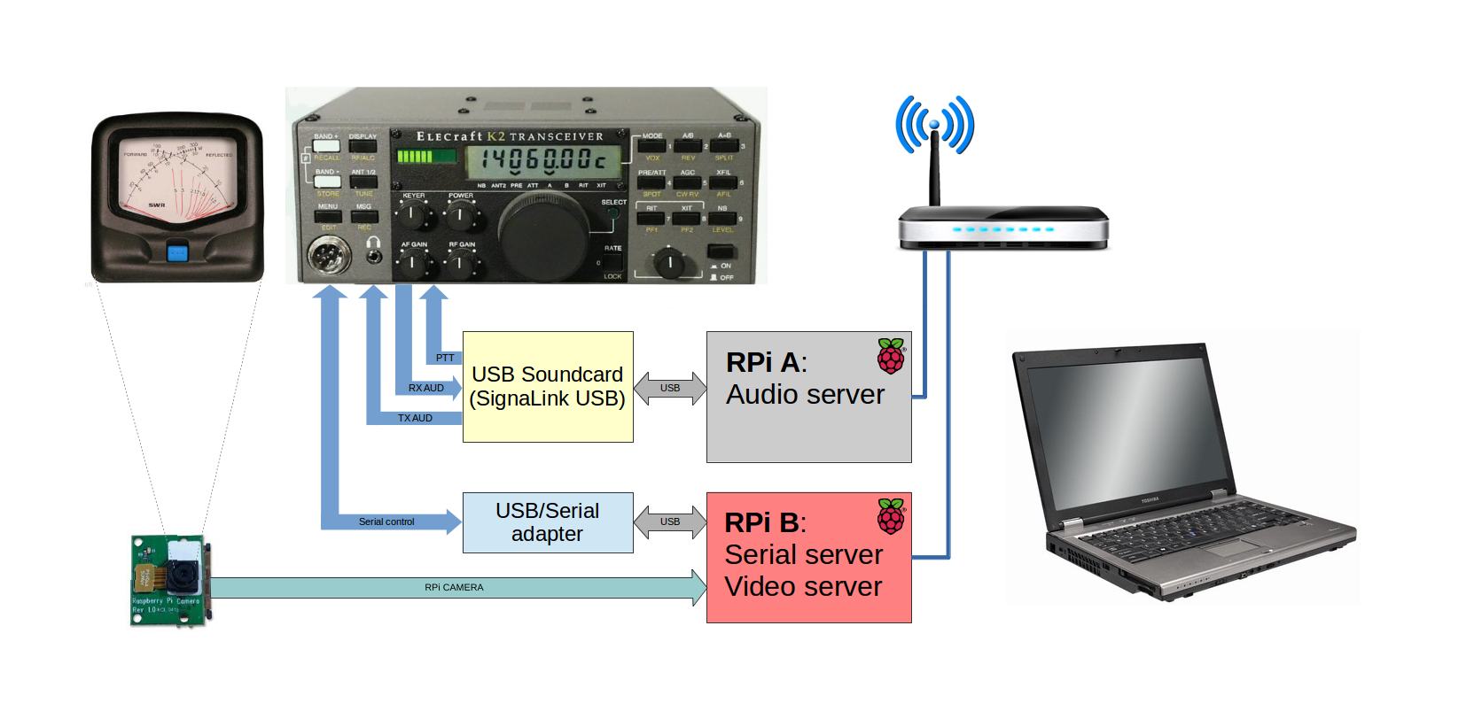
The general idea is shown here:
There are three main functions implemented to enable operation of the radio remotely at a client PC:
- Audio server – This allows routing of receive and transmit audio between the radio and client PC applications. Radio PTT is generated by a VOX circuit on the Tigertronics SignaLink USB soundcard;
- Serial server – This allows connection of a virtual serial port on the client PC to the radio’s remote control interface giving full control of the radio’s functions;
- Video server – This allows live monitoring of a cross-needle Power/SWR meter improving operator feedback and confidence.
For starters I have split the tasks between two Raspberry Pis. During initial experimentation I found problems running audio and serial traffic simultaneously on one Raspberry Pi, probably down to the limitations of the shared USB/Ethernet bus. Adding a second Raspberry Pi and splitting the tasks overcomes this problem but I may try experimenting with the more powerful BeagleBone Black in the future.
There are many ways you could set up this system, I have tried some of them. I mostly use Linux as my daily Operating System and this page offers a guide as to how I use a Linux PC to operate the radio. The same thing can probably be achieved with a Windows PC or Mac, I just haven’t tried yet. In some respects it is easier to use a Linux PC for this because you are using the same applications that are running on the Raspberry Pi. My detailed (and rambling) notes made while setting up this project can be found here because some of the ‘trial-and-error’ notes and references may be useful further reading. Notes on my current setup are as follows…
Client PC
Laptop (Dell Inspiron 17 5000) running Linux Mint 17 Cinnamon-edition. On the radio I operate digital modes almost exclusively and that lends itself well to this setup. I use FLDigi for digital modes and AB3AP’s excellent K2 Control java application for radio control.
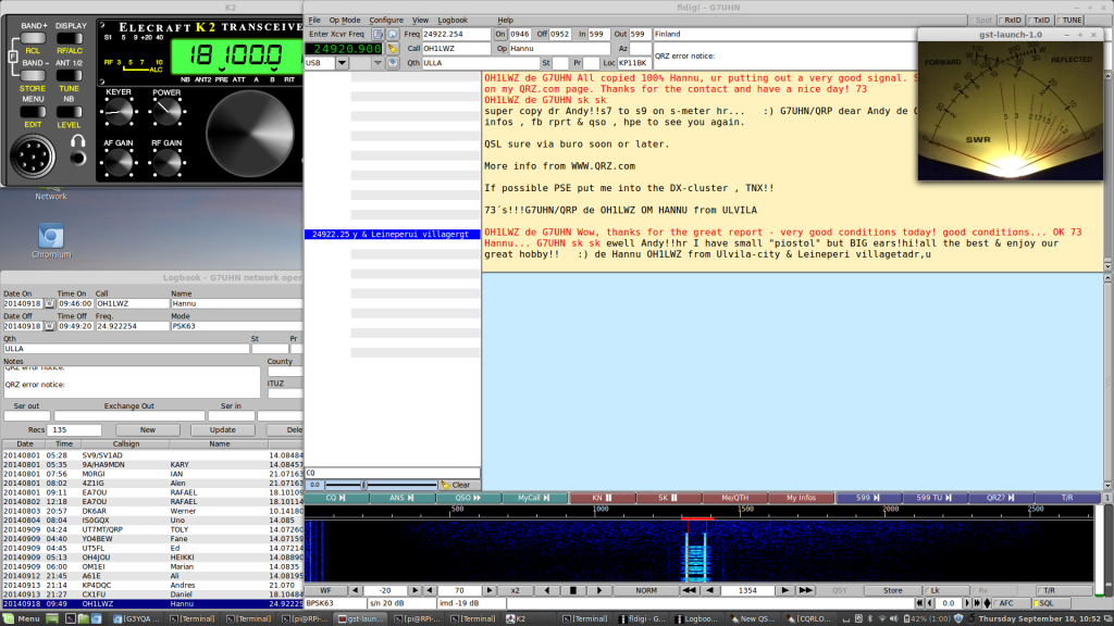
Some points to note on operating the station:
- My operating position is within a few steps of the radio equipment – in case of any undesirable transmit condition (e.g. stuck PTT) I can manually turn off the transmitter.
- Having a strong wifi signal avoids laggy audio glitches across the network (for me that means connecting the client PC to my 5 GHz wifi network while the plethora of other household devices use 2.4 GHz, the client PC is also sited fairly close to the wifi router).
- Currently only one application in the client PC can access the virtual serial port at a given time. A future improvement will be to allow other applications to connect to and monitor the virtual serial port and thus provide improved logging and station control e.g. K2 Control application controls the radio while FLDigi and/or logging application monitor the radio frequency and mode. NOTE TO SELF: Need to fix multiple access to the serial port to allow fldigi to pick up the frequency and mode to streamline logging…
Serial Server
There are two obvious ways to create a serial proxy server on the RPi, ser2net and socat. I use ser2net to run the server at the RPi and socat to connect at the client PC. This RPi runs the Raspbian distribution.
On the RPi:
Install ser2net on RPi. Create or modify /etc/ser2net.conf with these lines (modify as necessary to suit your desired serial port parameters):
BANNER:banner:Serial-USB Proxy Server: 4800 baud, 8, none, 2 (Elecraft K2)

4001:raw:0:/dev/ttyUSB0:4800 8DATABITS NONE 2STOPBITS banner
This makes the USB-serial adapter’s port available on the IP network at the RPi’s IP address, port 4001.
On the Linux client PC:
socat can connect to ser2net configured as above with this command:
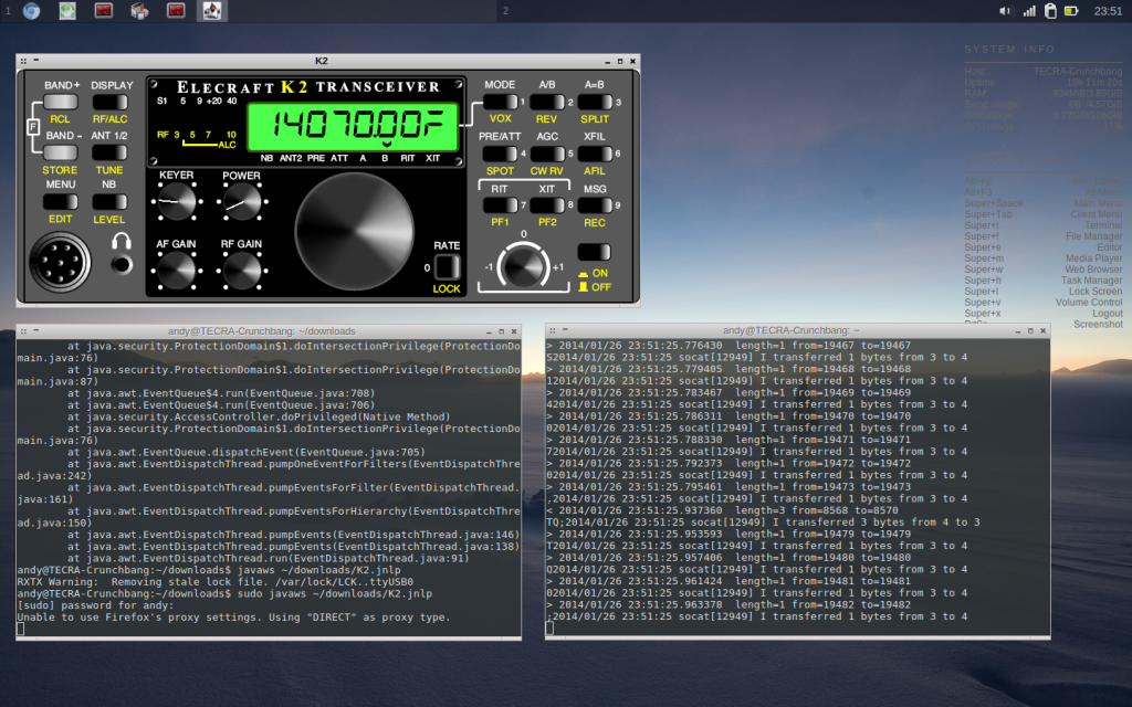
sudo socat -v -d -d -d TCP4:YOUR_RPI_ADDRESS:4001 PTY,link=/dev/ttyS1,b4800,cs8,cstopb=1,parenb=0
From this point a virtual serial port on the client PC, /dev/ttyS1, is attached to the USB-serial adapter on the RPi. Note, I have a hardware serial port on my laptop that is already registered as /dev/ttyS0, if you don’t already have something registered there you may need to use this address instead.
AB3AP’s excellent K2 Control java application runs perfectly in Linux and when run as root can connect to the ttyS1 port giving me full control of the K2, filters, menus and everything. I have implemented mousewheel-scrolling of the dial frequency using easystroke, a gesture recognition application for Linux that can also be used for mapping mouse buttons to keys and a Logitech gaming mouse with some programmable extra buttons.
Audio server
This RPi runs the Pidora distribution (this is to ensure availability of pulseaudio version 4.0 or later) so things are a little different in setting up (Pidora is a derivative of the Fedora distro and uses the yum package manager). I have a Tigertronics SignaLink USB soundcard connected to the RPi. On the RPi, I use pulseaudio to create an audio sink and audio source for the soundcard’s line out and line in and these are published on the local network. Once this is running, the sink and source are made visible at the client PC and can be accessed by applications.
On the RPi:
After installing Pidora and setting up the basics (create a “headless” file in the boot partition including the “RESIZE” command to resize the rootfs partition and allow installation of further packages, check reserved IP on DHCP server, boot, log in, yum update, create pi user, add user to audio and pulse groups…), install pulseaudio and a few other things:
yum install pulseaudio pulseaudio-module-zeroconf alsa-utils avahi
Modify /etc/pulse/daemon.conf to set exit-idle-time = -1 to stop pulseaudio timing out.
Modify /etc/pulse/default.pa to include (or un-comment) these lines:
load-module module-alsa-sink device=hw:1,0
load-module module-alsa-source device=hw:1,0
load-module module-native-protocol-tcp auth-ip-acl=127.0.0.1;192.168.1.0/24
load-module module-zeroconf-publish
…and comment out the lines that automatically load device in favour of the manually specified USB device above:
### Automatically load driver modules depending on the hardware available
#.ifexists module-udev-detect.so
#load-module module-udev-detect
#.else
### Use the static hardware detection module (for systems that lack udev support)
#load-module module-detect
#.endif
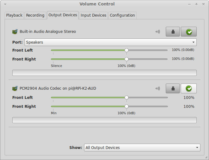
I now start “pulseaudio -vvv” on the RPi (the -vvv option gives the full commentary to provide some clues as to what’s happening, once comfortable that it’s working I reduce this to just ‘-v’). Very quickly after this, the source and sink appear in my client PC volume control (pavucontrol) as “PCM2904 Audio Codec on pi@RPi-K2” under the Input Devices and Output Devices tabs.
Quality of the receive audio (RPi to Client PC) has been improved by applying this firmware downgrade to the RPi:
sudo rpi-update eeb2e51c3e08cd5efa4246aa8dc54a09b25ada12
On the Linux client PC:
Install paprefs, run it and enable the following options:
- Make discoverable PulseAudio network sound devices available locally
- Enable network access to local sound devices
- Allow other machines on the LAN to discover local sound devices
- Don’t require authentication
My Fldigi sound configuration is to connect to a Pulseaudio server at “127.0.0.1” (the client PC’s local pulseaudio server which has discovered the audio source and sink over on the RPi audio server). Once Fldigi is running, open the system volume control panel (pavucontrol) and under the Recording and Playback tabs Fldigi can be connected to the audio source and sink on the RPi:
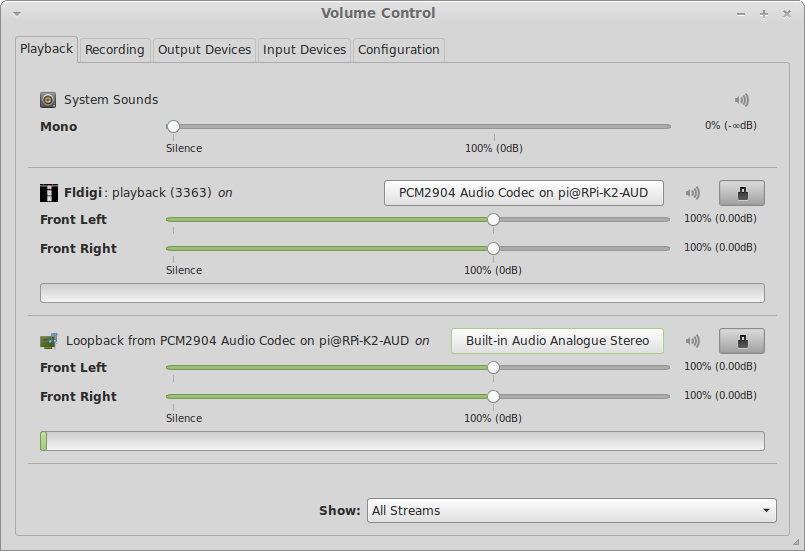
Local monitoring of the received audio (RPi source) can be achieved by loading the pulseaudio loopback module at the client PC:
pactl load-module module-loopback
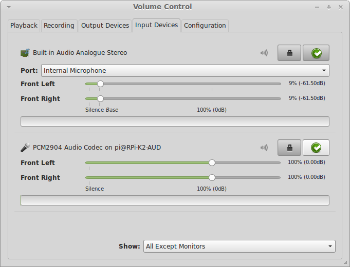
Under Playback and Recording tabs in pavucontrol select “Show: All Streams” and you can now choose a source for the monitor, in my case its my RPi audio source “PCM2904 Audio Codec on pi@RPi-K2-AUD”:
Video server
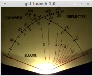
This part of the project may seem a little frivolous but a video feed included in the setup gives me important feedback on the real state of the radio’s transmission and indication if there is any problem with the transmission or antenna.
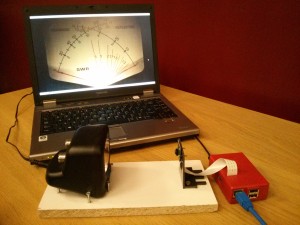
This RPi runs the Raspbian distribution. I have a Raspberry Pi Camera Module connected to the RPi. The RPi camera module is sold as a fixed focus camera but its lens is actually adjustable for focus if you break the glue applied at the factory as per this page, it’s not as scary as it sounds. I have adjusted mine for focus at around 10cm, the distance required for my power meter to fill the camera’s field of view and made a mounting base for the meter and camera from some off-cuts:
It is probably beneficial to minimise the bandwidth used by this stream to avoid interference to the audio stream (where performance is critical). For me, a video size of 320×240 pixels and a frame rate of 20 fps gives the minimum comfortable monitor of the meter.
TCP method:
This page shows how to set up the gstreamer server using TCP on the RPi, this page shows a command line for a Mac or Linux client that works for me at least.
On the RPi server:
raspivid -t 0 -h 240 -w 320 -fps 20 -b 2000000 -o - | gst-launch-1.0 -v fdsrc ! h264parse ! rtph264pay config-interval=1 pt=96 ! gdppay ! tcpserversink host=YOUR_RPI_IP_ADDRESS port=5000On the client PC:
gst-launch-1.0 -v tcpclientsrc host=YOUR_RPI_IP_ADDRESS port=5000 ! gdpdepay ! rtph264depay ! avdec_h264 ! videoconvert ! autovideosink sync=false
UDP method:
I have encountered occasional lock-ups of video using TCP and I now use UDP streaming which is more tolerant of the occasional network hiccup. This method requires that the client PC receiver is started before the server is commanded to stream to it in order to catch the stream’s header.
On the client PC, start listening on port 5000:
gst-launch-1.0 -v udpsrc port=5000 ! gdpdepay ! rtph264depay ! avdec_h264 ! videoconvert ! autovideosink sync=false
On the RPi server start the UDP stream, directed to the client’s IP:
raspivid -t 0 -h 240 -w 320 -fps 20 -b 2000000 -o - | gst-launch-1.0 -v fdsrc ! h264parse ! rtph264pay config-interval=1 pt=96 ! gdppay ! udpsink host=<your client IP> port=5000



Thanks for this article. I think it set me on the right path for getting pulseaudio to stream, as I’m looking to do a similar project with my mobile rig, being controlled via a CAT serial port, and using remote audio with fldigi.
Cool, glad you like it Corey, thanks for dropping me a line. Good luck, 73!
Andy, I do not see and email adr for you on QRZ, so will see if this message reaches you. I notice that you were looking to test your iCW / Mumble setup earlier this afternoon and discovered that none of K6KX, or W4TY, or myself (W5UXH) were actually listening in the room. K6KX is often in the room but never QRV except for our evening sked. W4TY usually does not remain in the room but he forgot to logout yesterday after our random QSO.
I usually have the speaker on, but am not always nearby and today I did not even have the speaker on. But if you check back, or better email me, I will be happy to try to give a hand checking out your setup. I am not QRV nearly as much as normal right now so there is less chance of catching me at random.
Mumble has a loopback mode where you can test independently, and it has a recorder utility that can be useful for testing also.
Chuck
Hey Chuck, thanks for dropping me a line! Don’t check these comments very often, I’ll mail you back shortly 🙂