A companion display and soft-keys for the FT-817
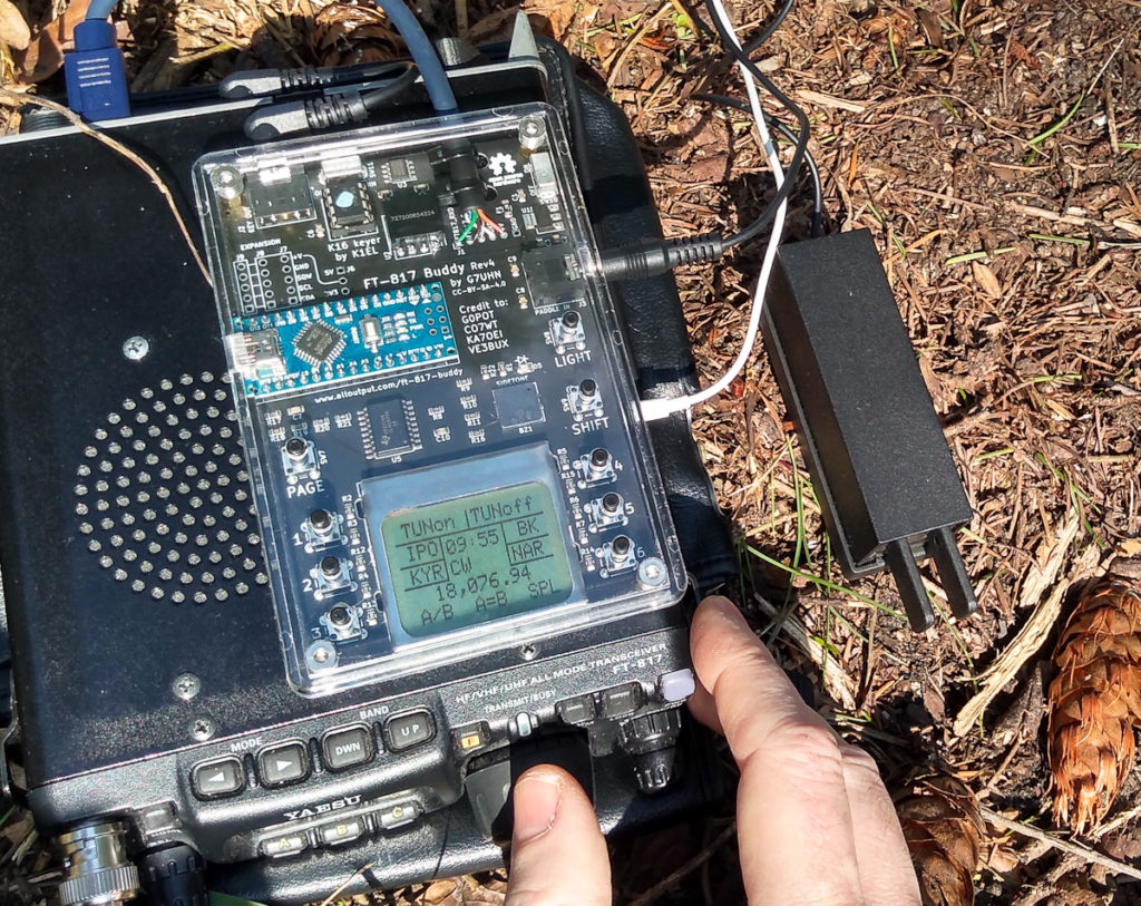
Welcome to my little DIY project I call the “FT-817 Buddy”. If you like what you see here and you want to replicate it for yourself, you’re in luck because I’ve written up all my design notes, shared all the files on GitHub and knocked up some instructions so almost anybody can build this thing. Much better than just a boring write-up of a thing I once built, right?
At a glance the Buddy might look rather complicated… but at its heart, this project is really just an Arduino, a display and a few buttons (and now K1EL’s keyer chip). I want people to see this simplicity and get stuck in.

I’ve designed it to meet my own simple needs (described below) and you might want something different. No problem because that is the joy of open-source projects – you are free to take this and modify it to suit your needs or feedback changes and improvements to the project. If you want to know more about the permissions, conditions and limitations of the Creative Commons Attribution ShareAlike license I have selected for this project, click on the link I just gave you. 🙂
Credit up front
- Clint Turner, KA7OEI, and all his contributors for clearly documenting the FT-817 CAT and EEPROM commands;
- James Buck, VE3BUX, for the FT-857 Arduino library that got this started;
- Michael Sansom, G0POT, for support, testing, videography (!) and putting up with an endless stream of DMs;
- Pavel Milanes Costa, CO7WT, for Arduino software library;
- Everyone who puts up tutorials on the Internet allowing us to learn new skills…
The Problem This Solves
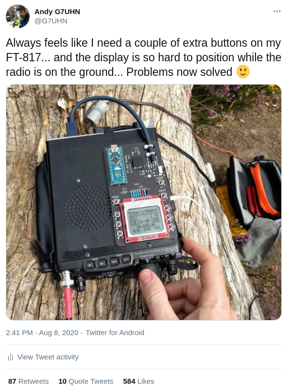
I like spending time with my FT-817ND in the great outdoors but it always seems like Yaesu’s choices of functions on the A,B,C buttons has me fiddling around on the tiny front panel when I want to lower tx power for a tune signal, raise power back up for QSO, switch the CW filter in/out, use the A/B and A=B keys to help me browse around the bands… I just need a few more buttons! So, I started thinking about adding a small control panel that could be programmed to send a couple of commands to the radio via the serial (CAT) port, maybe with a little display alongside some new buttons, effectively adding some new soft-keys. That thought quickly led me to KA7OEI’s amazing work in documenting the FT-817 serial command interface.
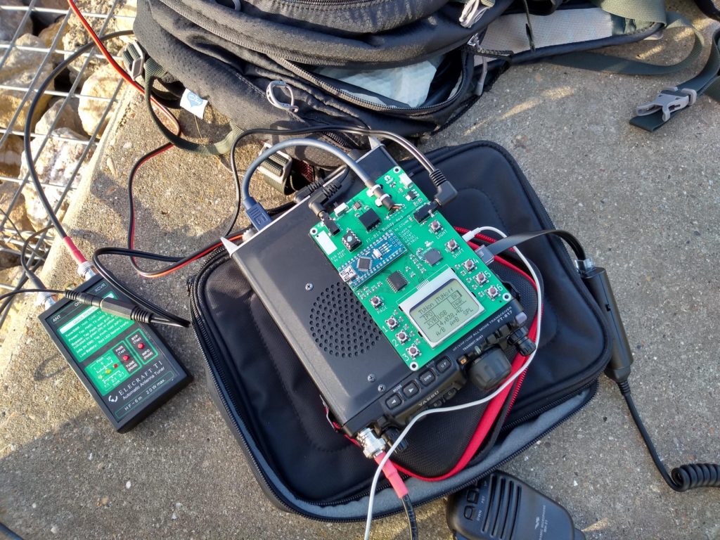
It wasn’t long before I was reading the FT-817’s frequency on a small display that was lying around the workshop (thanks G4ELM!). I then realised the utility of including some of the front panel information in a display that can be more easily read than the radio’s front panel when the rig is on the ground (my normal /P operating position). So, a bit of breadboard prototyping and a couple of KiCad tutorials later, voila:

Turns out this is quite a useful accessory if you’re a portable FT-817 operator (well, that was the idea, wasn’t it!) and people like this project so I’m sharing all the info and have packaged this up so you can replicate it. By doing so you’ll get a taste of some useful hardware and software stuff and maybe learn some new things to incorporate into your own projects. Remember, this is just a DIY project and not a fully-tested and warrantied commercial product so set your expectations accordingly.
Features
Not much has changed since the first PCB, it’s only meant to be a simple device that adds a few more buttons to your FT-817… but in Rev3 I added a K1EL K16 keyer chip which brings along a memory keyer (another feature the FT-817 lacks) and some cool CW functions. Features include:
- Display current frequency and mode
- Display current A,B,C key functions
- 3 pages of 6 soft-keys
- Backlight
- Tune signal on/off (Transmit an AM carrier, suitable for driving auto-ATU)
- Toggle IPO
- Toggle NAR filter
- Toggle Break-In
- Toggle FT-817 internal Keyer
- Toggle RF Gain/ Squelch
- Toggle VFO A/B
- Set FT-817 internal keyer to preset wpm (12, 15, 18 in my case)
External keyer: K1EL K16 chip integration
- Command and M1, M2, M3, M4 buttons
- Onboard piezo buzzer and LED for K16 feedback
- Control speed using CMD+paddle (K1EL’s “Fast Speed Change” feature)
Rev4 now has an expansion header:
- Pins for an Arduino I2C port and hardware interrupt pin are broken out on the PCB
- Pins have been laid out for easy connection to the SparkFun DS1307 Real-Time Clock module (part number BOB-12708)… no need to enter the time after power-on 🙂
- Patch area on the PCB allows reconfiguration to match other modules e.g. a GPS/GNSS receiver module
Of course all sorts of functions and macros are possible, you just need to write the Arduino code for what you want. What’s been done already should provide good examples for people to follow and that’s all part of the fun of this project.

Health Warnings
Let’s talk about risk and responsibility. Yay!
I offer this information as a DIY project. That means you’re going to do it yourself, right? So you need to make sure you’re comfortable with the material and you’re able to support yourself as you go. The cost of PCBs, components and delivery charges make this most economical for groups builds so you should find some friends to help. Read the documentation here on this site before you dive in. This project covers some great topics (microcontrollers, serial data, PCB design, software…) and there are plenty of Internet tutorials out there to help you learn and grow!
I make no claims that this is the best way to implement this idea. In fact I have very little circuit design experience and my software process is limited to copy/paste/Google the error message… so there is plenty of scope here for modification and improvement.
Most importantly, the documented CAT commands for the FT-817 are pretty limited in what they can do. The main feature I wanted to control on my FT-817 (switching CW filter) requires use of the undocumented EEPROM commands. As KA7OEI wisely points out (at least six times!) incorrect manipulation of the EEPROM may result in an unusable radio and require you to re-enter all of the 76 factory alignment values (which you obviously take the time to record for your individual radio before you try this!). Worst case scenario might be bricking your FT-817. If I did that to mine I would shed a tear, think about the experience and then buy a KX2, I’d get over it. If you don’t feel the same, now is probably the right time to stop reading…
What Work Am I Going To Have To Do?
To replicate what I’ve done all of the steps should be in the Build Instructions. It pretty much boils down to:
- Order some PCBs using the files provided. You can even have most of the small SMD components added at the factory! Boards are typically ordered in multiples of 5.
- Buy the rest of the components listed in the Bill Of Materials. As well as the PCBs, some of the components may have minimum order quantities (MOQs) from your favourite suppliers so this project works better as a small group build;
- Build it. Some of these components are surface-mount but easy sizes so this is a great opportunity to gain some experience if you haven’t already. You can watch this video of soldering the SMDs that can’t be factory-fitted in order to judge the difficulty. I believe in you. You can do this.
- Load the software onto the Arduino. The Arduino code is over at GitHub. I won’t implement every possible function so you may have to roll your sleeves up to get the functionality you want…
Some notes on building a case around this thing can be found under Enclosure Notes.
A useful modification you might make to your FT-817 is the VK4GHZ +12V Accessory Connector mod. This bypasses the current-limiting resistor on the ACC port and makes the +V output on the ACC connector switched with the radio power (rather than always on). I’ve done it, it’s a bit tricky.
If you want something different your work may include these kind of steps:
- Review the KA7OEI FT-817 commands page. Have a think about what commands you want to work with and how those commands work with the FT-817 interface – you’re probably going to be modifying the Arduino code to suit your needs but the chances are one of the commands we’ve already implemented is a close match and you’ll just have to substitute some values, do some copy/paste stuff. Bear in mind the warnings about minimising EEPROM interaction to avoid wearing it out;
- Review the schematic and PCB layout (KiCad hardware files are on GitHub). Maybe you want to use a different display or a different layout of buttons. Maybe you want to reduce the current consumption. You can redesign it to meet your needs!
- If you’re thinking of adding new features to the device, it might be wise to get the components in and experiment with the circuit on breadboard first. That way you can see if the microcontroller has enough memory for your modified code before you solder one to a PCB. Right now, the Arduino Nano is looking pretty full so this is a real possibility (on 27 Feb 2021, RAM 82%, Flash 72%).
- If you take this design and build on it, remember that it’s Creative Commons Attribution ShareAlike… so give credit where it’s due and share your stuff for everyone’s benefit. Go for it!
Tutorials I Have Followed
We’re all beginners at some point. To put this together I just learned a bunch of stuff from Internet tutorials and mashed it together. Mostly these ones:
- Get an OLED display running on Arduino
- Drawing on OLED displays
- Nokia display with Arduino
- Arduino timer interrupts
- Using the B0505S-1W and ADUM1201 for DC and data isolation
- KiCAD schematic and PCB tutorial
- Using JLCPCB’s SMD service from KiCAD
- KiCAD and FreeCAD integration to design enclosure
Over To You…
That’s pretty much it, links in the sidebar to the project sub-pages should tell you everything you need to know, especially the FAQs. 😉
Enjoy!
Andy G7UHN

This work is licensed under a Creative Commons Attribution-ShareAlike 4.0 International License.

Hi there,
As I am extraordinarily lazy (and hate surface mount), is there anyone selling an assembled version?
regards
Stephen G7VFY
mister35mm (at) yahoo.co.uk
LOL! Hi Stephen. At this time there’s no fully assembled version (if that changes I’ll drop you a line). Your best option is to order the PCBs from JLCPCB where they can solder on all of the SMT components except for the 5 LEDs and the buzzer. The pads are of a pretty forgiving size for hand-soldering and Michael G0POT has done a demo of soldering these components on here: https://www.youtube.com/watch?v=k9kuWy1ynIs
Also, Robin G7VKQ has done an alternative technique on this video here: https://www.youtube.com/watch?v=1qxtlcZElow
Also bear in mind that because the PCBs are ordered in multiples of 5, most people will do this project as a group build. When you’ve gather up a group, if you have the PCBs delivered to the person most comfortable with soldering SMT then they could pop those components on for you, that’s what a few others have done.
Hope you get a team together and good luck! 🙂
Since your board already has SMD devices, why not just include the Atmega328 right on the pcb and skip adding a complete Arduino?
Cheers
Dave AA3EE
Fair point Dave. Might be fun when I fancy levelling-up my PCB skills, good thinking. 🙂