…or “Living Without A Shack: Part 3”!!
This page is a follow-on from my original page of notes on my efforts on setting up networked receivers in the house, mainly based on VNC operation of a PC running low-cost SDRs in the loft. The loft PC-based operation has proven a little cumbersome for my liking and the new setup tackles the following points:
- SoftRock HF receiver performance is good but the PC that runs it in the loft is noisy and can’t be switched on at night time without waking my wife! Need something silent;
- VNC operation of the PC can feel a little cumbersome, want to try running the SDR application on the PC in front of me using receivers streaming I/Q over the network;
- Need to have access to RTL-SDR dongles for reception – obviously these are low-spec receivers but I’m starting to look at some technology work with schools so it’s important that I understand what can be achieved with these simple low-cost devices;
- Adding an external antenna will improve VHF weather satellite reception but should be in keeping with my aims of low visual impact.
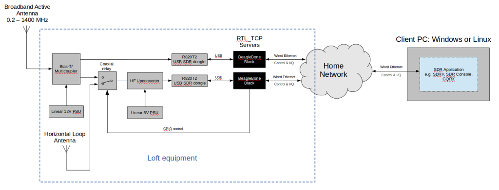
So what does the new network receiver setup look like? Something like this:
The new setup is very quick to activate. The BeagleBones run silently 24/7 in the loft, either (or indeed both) can start RTL_TCP server in just a few seconds through an ssh connection and, on the client PC running either Windows or Linux, I am getting good results with SDR#, SDR Console v2 and Gqrx.
Antennas
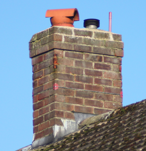
Starting at the top of the system, I now have a Cross Country Wireless Broadband Active Antenna, discreetly mounted on the chimney:
Much less visible than the usual wideband discone antenna and provides coverage from 200 kHz to 1400 MHz. Obviously it’s not going to be the greatest performer across this entire frequency range but should provide adequate performance for general coverage. Further specialist antennas can be added later on if required.
- Painted with red oxide primer to reduce visual impact;
- Protected against co-site transmissions from my other loft antennas;
- Good V/UHF omni reception – strong signals from LEO weather satellites within a few seconds of appearance above the horizon… this video shows reception of NOAA 15 and NOAA 18 during a low angle pass;
- Provides two outputs to receivers, I feed into an HF and a V/UHF receiver;
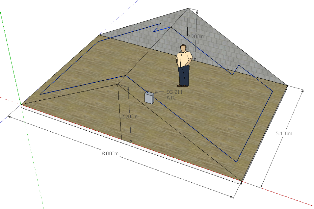
A second antenna for HF reception is a horizontal loop of wire around the perimeter of the loft, about 28m in circumference. It is connected to the HF receiver via a 9:1 balun. The HF receiver can be switched from one antenna to the other by a coaxial relay.
Receivers
The two outputs from the antenna feed two RTL-SDR dongles, one of which is coupled to an HF upconverter:
- 27 – 1400 MHz coverage provided by a R820T2 dongle from RTL-SDR.com
- 200 kHz – 30 MHz coverage provided by a Ham It Up 1.2 upconverter and a second R820T2 dongle from RTL-SDR.com
Both of these dongles are connected to BeagleBone Black single-board computers used as RTL_TCP servers so they can be accessed by SDR applications being run on any PC on the home network. Performance of streaming RTL_TCP traffic across the wireless network is flakey so the wired network has been expanded to add a few more sockets around the house.
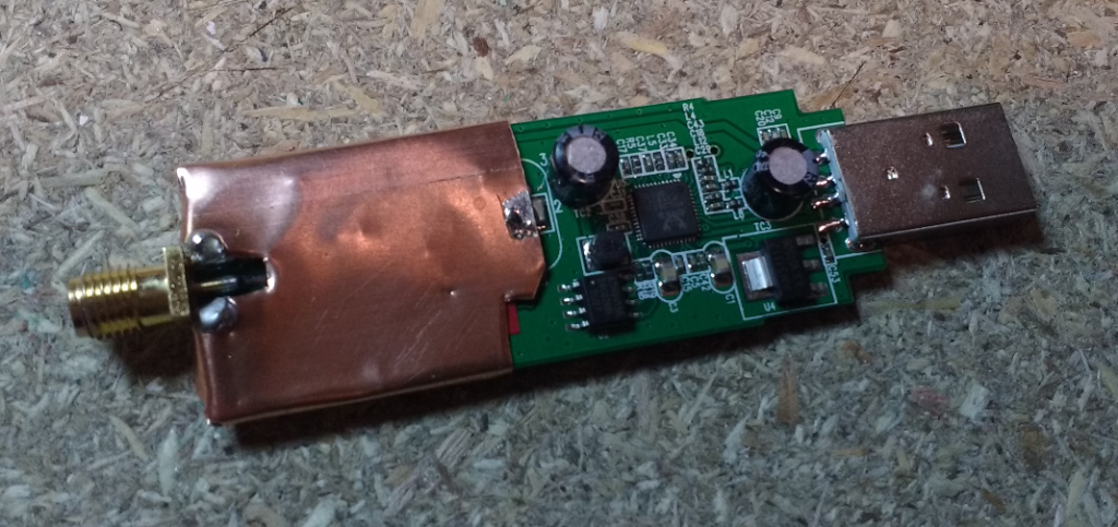
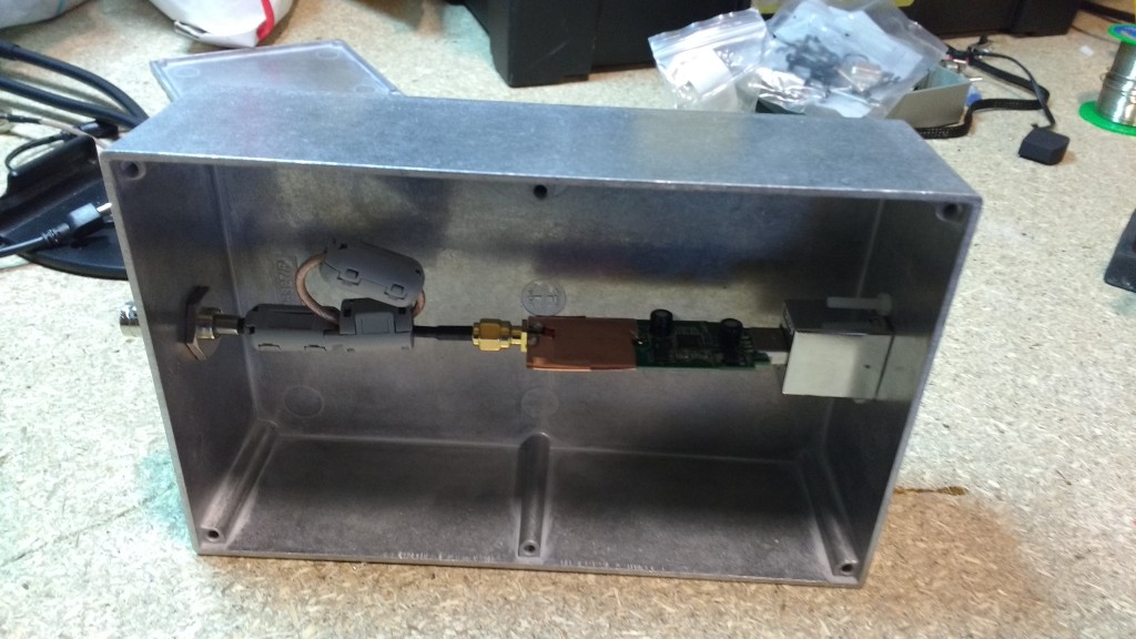
The dongles have been shielded and boxed as per the ideas on Martin G8JNJ’s page on SDR (quite a way down the page!) where he describes modifications made to the RTL dongles used in the Farnham WebSDR (coincidentally located just a few miles from my house so makes a useful comparison for satellite reception).
Networked operation
Each of the RTL dongles is plugged into a BeagleBone Black running Debian (Image 2015-11-12). At this time, the setup of the RTL server requires compiling the driver from source and, because I do this infrequently (and thus always forget how to compile stuff on Linux!), my command sequence is listed below:
sudo apt-get install git cmake libusb-1.0-0.dev build-essential
git clone git://git.osmocom.org/rtl-sdr.git
cd rtl-sdr/
mkdir build
cd build
cmake ../ -DINSTALL_UDEV_RULES=ON
make
sudo make install
sudo ldconfig
cp ../rtl-sdr.rules /etc/udev/rules.d/
Once the driver is configured on the BeagleBone Black the servers are activated by the simple command:
rtl_tcp -a <insert server's IP address>
Once the server is activated then it is available for client applications to connect to it across the network.
I did initially have some problems with rtl_tcp and tried rtl_rpcd as an alternative. That was successful but rtl_tcp seems to be running well for me since a rebuild of my Linux client PC. Currently I’m having good results with SDR# and SDR Console v2 on a Windows 10 client PC and Gqrx on a Linux client PC.
A useful addition to the setup is the antenna switching coaxial relay that is controlled by a GPIO output from the HF receiver’s BeagleBone Black and a CircuitCo Relay Cape to switch the coaxial relay’s coil on and off. This allows me to quickly toggle between antennas to determine the best one for reception of a given signal at HF.
…a quick note about network throughput…
It didn’t take long to figure out that running the dongles across a wireless network has some fairly big limitations. Let’s have a quick think about basic requirements of the I/Q stream from the RTL dongle…
At the 2 MHz sample rate:
8-bit ADC sampled for both I and Q signals (multiply by 2) at 2 MHz = 32 Mbps (not accounting for any overheads)
At the 250 kHz sample rate:
8-bit ADC sampled for both I and Q signals (multiply by 2) sampled at 250 kHz = 4 Mbps (not accounting for any overheads)
…and how fast do you think your wireless network runs? Well, probably a lot slower than you think. You can get an idea of realistic network throughput speeds by using a tool like iperf. As an example, my home wireless network gives me throughput speeds up to about 20 Mbps when sat about 6m from my 802.11ac Netgear R7000 router (which claims to give up to 1300Mbps!) on the 5 GHz network that is reserved for amateur radio activities (e.g. streaming between PC and radio), all of the domestic wifi chatter (laptops, iPad, smartphones, etc.) is run on the 2.4 GHz network. Your wireless network throughput will be heavily dependent on the distance the wireless signals have to travel, the performance of the antennas at either end of the link and also the number of other devices sharing the network and what their network demands are. That’s really another topic but the point is that you should have a realistic understanding of what can be expected of a wireless network – even with the care I’ve taken to separate the domestic network from amateur radio activities, I can only reliably stream I/Q traffic from an RTL dongle at the lowest sampling rate (250 kHz) across my wireless network to my normal operating positions (your mileage may vary!).
Instead of using wireless networking for this activity, I have expanded my wired network in the house to give me reliable Gigabit speeds. Using wired networking means there is no problem with streaming I/Q from both the V/UHF and the HF dongle server simultaneously.
APRS Receive-only iGate
The V/UHF dongle is often left running as a receive-only APRS iGate tuned to the normal UK packet frequency, 144.8 MHz. Because the dongle and BeagleBone Black had already been set up with rtl-sdr it was a remarkably quick process to get this running thanks to the excellent guide by G6NHU. I followed his process to install and configure direwolf, only missing out one line of Raspberry Pi specific configuration.
Electrical noise reduction
Some attention has been paid to reducing electrical noise generated by Ethernet hardware and switch mode power supplies around the house, see this page for further details. Because of their sensitivity to electrical noise, both the active antenna and upconverter are powered by linear power supplies. The active antenna is supplied 12 VDC from a small linear PSU supplied by WinRadio. 5 VDC linear power supplies are more difficult to buy at reasonable cost (the audiophile market seems to have had an effect here as they will pay crazy prices for clean 5 VDC to power their DACs). I happened to have one of these Mascot PSUs which came to me in a clear-out at work but if you know of a good source of low cost 5 VDC linear PSUs please leave a note in the comments below…!
Some examples
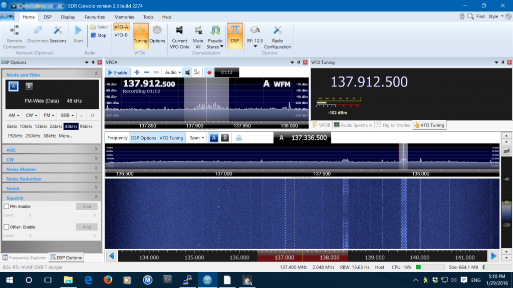
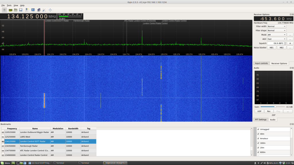
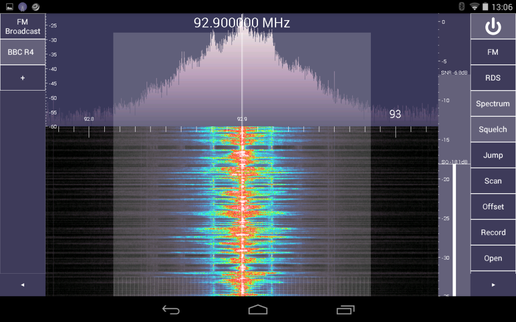
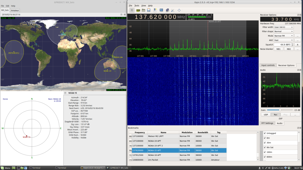
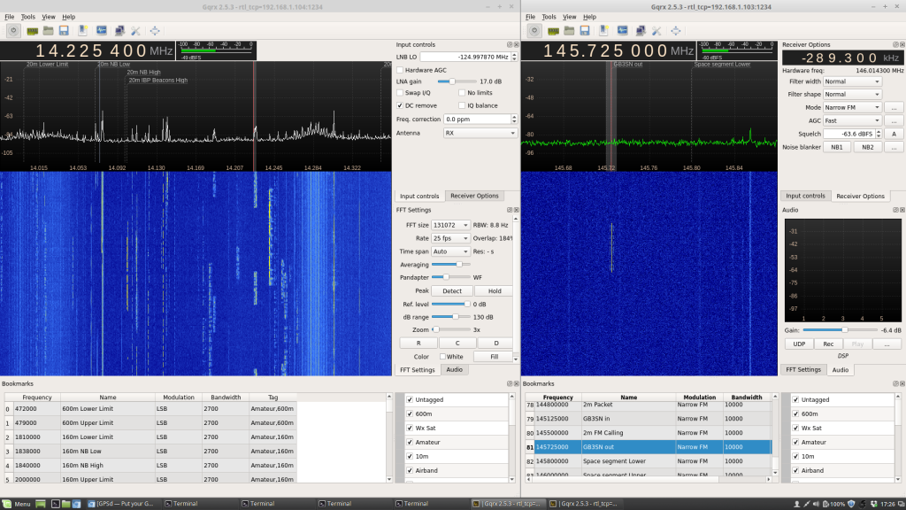
Some example screenshots of HF broadcast and amateur, 2m, 70cm, weather satellites…
