This is a page to document my efforts on connecting a Garmin eTrex H to a Yaesu VX-8DE radio to provide GPS-derived position input to the radio’s APRS modem. Ultimately the Garmin receiver gets replaced with a low cost GPS receiver module (read on!) but the interesting thing about this project is most likely the use of the Arduino(s) for some NMEA-0183 message translation…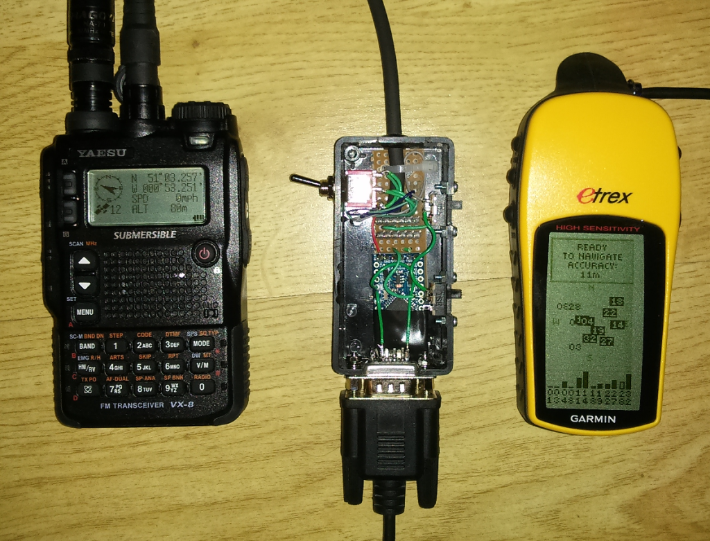 Having aquired a Yaesu VX-8DE, I’d read I could provide GPS position to the radio via an external NMEA 0183 source so I figured I’d use my old Garmin I had lying around the house and avoid the very expensive Yaesu GPS unit. Only on digging deeper into the subject did I find out the the VX-8 doesn’t take a standard NMEA feed, it requires some conversion. All credit to Taylor J. Meek for his page on reverse-engineering the Yaesu’s interface to determine what’s required. Taylor’s page has all the detail but, in summary:
- The Yaesu radio requires 9600 baud TTL 3.3V signalling (not the 4800 baud RS-232 signalling used in the NMEA 0183 standard);
- The Yaesu radio requires NMEA sentances to be zero-padded out to maximum lengths otherwise they will be ignored by the radio.
No problem. I had an Arduino Uno lying around the house looking for a project and this seemed like an ideal thing for it to do – translate between the Garmin’s NMEA output at 4800 bps and the VX-8 input, correctly formatted for Yaesu, at 9600 bps. It’s worth noting that David Fannin has also posted some Arduino code and documented his project to achieve a similar result. Simply using David’s code didn’t achieve my aim of learning some more about Arduino and we also have slightly different systems at the end – David has a self-contained battery-powered GPS module for his VX-8, my page here finishes with a small box to translate between legacy GPS units and is powered from the VX-8 radio’s 3.3V output.
Prototype: Arduino Uno
Not having used an Arduino before (or any other microcontroller for that matter) I started with some baby steps, breadboard and a Yaesu CT-M11 cable for the radio interface (a Yaesu clone cable can be cut in two to give you two data cables for the VX-8 but I eventually wanted to use its 3.3V output to power the Arduino and the CT-M11 cable seems to be the only way to get all the pins wired on a Yaesu connector).
The basic form of the sketch is to set up a software serial port in addition to the hardware serial port already on the Arduino. This gives me two serial ports, one of which can operate at 4800 bps (NMEA standard data rate), the other can operate at 9600 bps (VX-8 data rate). I use the TinyGPS++ library to listen to the NMEA input from the Garmin unit and extract the various GPS parameters from the incoming NMEA sentances. I then construct my own “GPGGA”, “GPRMC” and “GPZDA” NMEA sentances in the zero-padded format required by the VX-8 and send out to the hardware serial port that the VX-8 is connected to. I use another library, TimedAction, to perform this event every 2 seconds (I had some problems using the simpler delay(2000) method in the early stages, that could well be fixed with this final sketch but I haven’t tried, TimedAction seems to work well).
The hardware is connected as follows (forgive the messy diagram!):
The two other devices (Sparkfun RS-232 Shifter and Logic Level Converter) in this prototype setup perform level conversion between the RS-232 Garmin output (which actually operates at 3V), the 5V Arduino Uno and the 3.3V TTL VX-8 radio serial port. There are a few ways you could do this, this is just what came easily to hand.
The Arduino sketch is listed on this page. Note the “SoftwareSerial…” line that must be selected based on which Arduino device you use.
In a box: Arduino Pro Mini
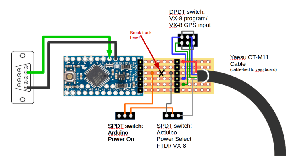
After a successful prototype I decided to put this into as small a box as possible and change to an Arduino Pro Mini running from the radio’s 3.3V output. The use of an Arduino Pro Mini allows the whole system to run at 3.3V so the Arduino can be powered from the radio’s 3.3V output and also negates the need for any level conversion (both the Garmin and the VX-8 input and output serial data at 3.3V). I also decided to make the device capable of using an FTDI cable to program either the Arduino (should any code revisions be required) or the VX-8 (for memory upload/download to PC).
This device has three functions:
Program Arduino: Connect FTDI TTL-232R-3V3 cable, do not connect radio, select Arduino power from FTDI cable, Arduino Power On
Program VX-8 Radio: Connect FTDI TTL-232R-3V3 cable, connect radio, Arduino Power Off, select VX-8 program (ensures tx/rx is the correct match between PC and radio)
VX-8/ GPS interface: Connect GPS, connect radio, select Arduino power from VX-8, Arduino Power On, select VX-8 GPS input (ensures tx/rx is the correct match between Arduino and radio)
The crucial difference between this Arduino Pro Mini setup and the prototype on the Arduino Uno is that, by default, the Pro Mini appears to expect TTL data to arrive on the software serial port. TTL and RS-232, as well as having different voltage levels, actually have opposite polarity for 1’s and 0’s so a bit inversion is required on the software serial port to account for this. Without performing the bit inversion the Garmin’s NMEA output (RS-232 alebit at 3V…) will appear to be garbage to the TinyGPS++ function on the Pro Mini. The Arduino SoftwareSerial function can has a parameter to enable bit inversion when required and this needs to be invoked here. My sketch has a comment line directing you to comment/uncomment the appropriate line setting up the software serial port for either the Uno or the Pro Mini. If you’re having problems with the TinyGPS++ function correctly decoding NMEA sentances, check this.
CAUTION – I’ve seen pictures of Arduino Pro Minis with the FTDI header pins both ways around. You need to check your particular device and match the colour/function labels printed on your PCB to the pins/wires you are going to use. Make sure you connect it the right way round!
Final (?) config: “Ultimate” VX-8 Connection Box…
Since putting the GPS/Arduino/VX-8 system together last year I’ve had a few thoughts on improving the setup:
- Put it in a metal box to reduce some of the RF interference (?) from the Arduino that can cause the radio squelch to break when the Arduino is close to a handheld antenna;
- Add a headset/handset socket to the box to maximise feaures of the system (and get best value out of my investment in the expensive Yaesu CT-M11 cable!);
- Cut down the length of the cable and maybe add a belt-clip to make it more suited to personal operation.
I was putting together a shopping list of bits to buy when I spotted a tiny Sparkfun GPS receiver module for £15 and thought I might as well cram in the GPS receiver to the final unit, further reduce the complexity and cabling and free up my Garmin for other duties. This GPS receiver module works off the same 3.3V the system is already using and provides a TTL output at 9600 bps. I did wonder if its NMEA output might be zero-padded and therefore directly compatible with the Yaesu radio… but it isn’t. So, the Arduino Pro Mini stays in the system and the Arduino code was simply tweaked to change the GPS serial interface from 4800 to 9600 bps and remove the bit inversion because the whole system is talking TTL now. Current consumption of the GPS module and Arduino Pro Mini together is about 40-55 mA, spending more time around 40 mA once the GPS has a satellite fix.
I chose to wire up the headset interface to be compatible with the old Icom ‘twin pin’ connector, partly because I had a headset and a handset lying around that both had that and partly because the 4-pin TRRS jack sockets that are common for Yaesu radios seem very difficult to get hold of in a metal chassis-mount configuration. I also found through trial and error that the 2k resistor that Yaesu suggest in parallel with the Mic/PTT and GND lines doesn’t work for the Icom headset, I found that a value of 4k3 worked for me to key the radio correctly.
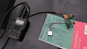
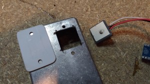
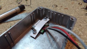
Some pictures of the latest (final?) version:
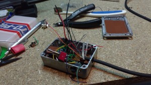
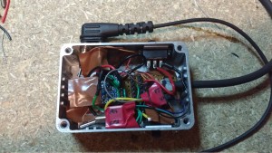
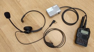
Summary
So, the end result is a neat little box (well, neat on the outside anyway…) that gives me:
- A GPS input to the VX-8’s APRS modem;
- A headset/handset interface to the VX-8 radio;
- A memory programming interface to the VX-8 radio.
In use (needs update!)
Arduino interference to the radio’s audio:
- Noise from the Arduino is audible on the mic line whether using an external headset/handset or the radio’s internal mic on the front panel. A recording of how the radio sounds on-air using the internal mic with Arduino on and off:
- Because the noise is audible even using the internal mic I suspect either
- Noise is a product of the Arduino drawing its power supply from the radio, or
- The external mic line on the handset connector is active together with the internal mic and noise is coming in on this line…
- Noise is also audible very quietly on the headset earphone, probably from cross-talk within the CT-M11 cable.
I can probably live with the noise for now as I can simply turn the Arduino off during voice operation but I may look at eliminating this, I expect a capacitor in the right place will do the trick.
Some interference to the VX-8 received RF during serial bursts from the Arduino is audible and breaks the squelch if the Arduino Pro Mini is close to the antenna. It’s not a show-stopper (I’ve managed to send and receive a APRS beacons through the ISS). Thoughts at this time:
- Is this unique to the Arduino Pro Mini? Or is it because the Arduino is being powered from the radio? Try the Arduino Uno and try the Pro Mini on a seperate battery supply…
- Was it heard using the Elk antenna away from the handheld? Did it deafen my receiver for the ISS pass? Try Elk antenna listening on terrestrial packet, listen for the noise from Arduino and try some tx, see if it’s corrupted.


Hi Andy! Finally got ahold of a VX-8DR and like some users, desire to get GPS functioning. So far, I got a simply straight wired GPS for testing (no altitude received— Adafruit Ultimate GPS), but not yet gone done the path of programming an Arduino Uno and connecting all the bits to passively (?) retranslate NMEA sentences to Yaesu-friendly strings (that’s what we’re after, right?) Had you ever considered just adding Bluetooth (3.3V with an audio DSP; found an RN52 that may function that way) instead (to allow for more modern headsets to connect— and if I had to guess it’s simply wiring up the audio (R speaker/mic?) to the VX-8DR pins? If not, had you considered not putting in any switches and streamlining the whole lot? Thanks, and thanks so much for the detailed info!
Hi Jack, no never thought about BT for the VX-8. I didn’t go any further than this on mine and eventually swapped the VX8 for a Kenwood TH-D72.